Volvo DICE (clone) — Power Supply Repair Guide
Device: Volvo DICE diagnostic interface, green-PCB clone (a 1:1 copy of the genuine Teleca-designed Volvo 9513100 unit — same NEC relay, Renesas M32C MCU, AM29F200 flash, same power-section layout).
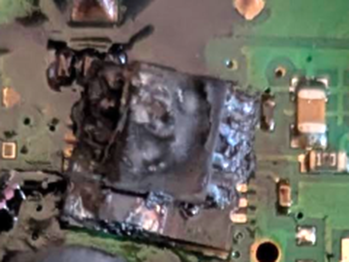
Diagnosis: the main switch-mode power supply IC — a Texas Instruments LM5000-3 flyback regulator (TSSOP-16 package) — has burned catastrophically. The rest of the board looks visually intact. This is a repairable fault, parts cost ≈ €10–15.
1. What happened
The LM5000 contains the 80 V / 2 A power switch that drives the yellow flyback transformer, generating the board's internal supply rails from the car's 12 V (OBD pin 16). Its internal switch failed short-circuit — most likely killed by a voltage transient from the vehicle (load dump / spike above the chip's 40 V input or 80 V switch rating), or simply a low-grade/counterfeit chip in the clone.
A shorted switch puts battery voltage straight across the transformer primary. A blob of melted silicon still has a few ohms of resistance — enough current to cook, not enough to instantly trip protection — so the chip burned until the yellow PolySwitch resettable fuse (UF250, 2.5 A / 30 V) heated up and cut the current. That fuse is why the digital side of the board very likely survived.
| Your board (burned) vs. genuine DICE reference |
|---|
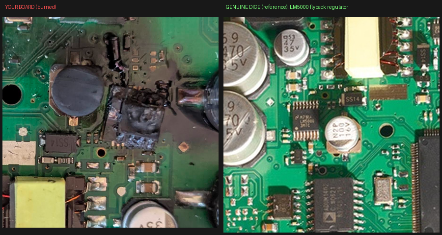 |
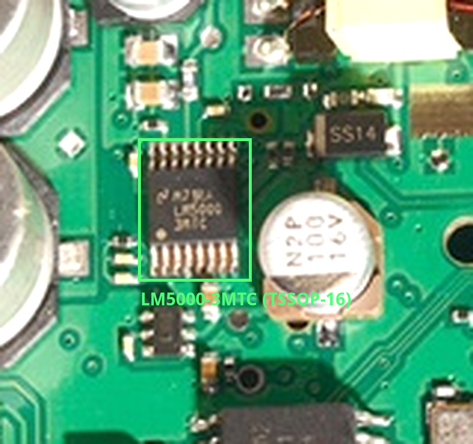
On the genuine board the chip marking is clearly readable at the identical location:
LM5000 -3MTC (National Semiconductor logo — NSC was acquired by TI; the part is still
produced by TI).
2. Component map of your board
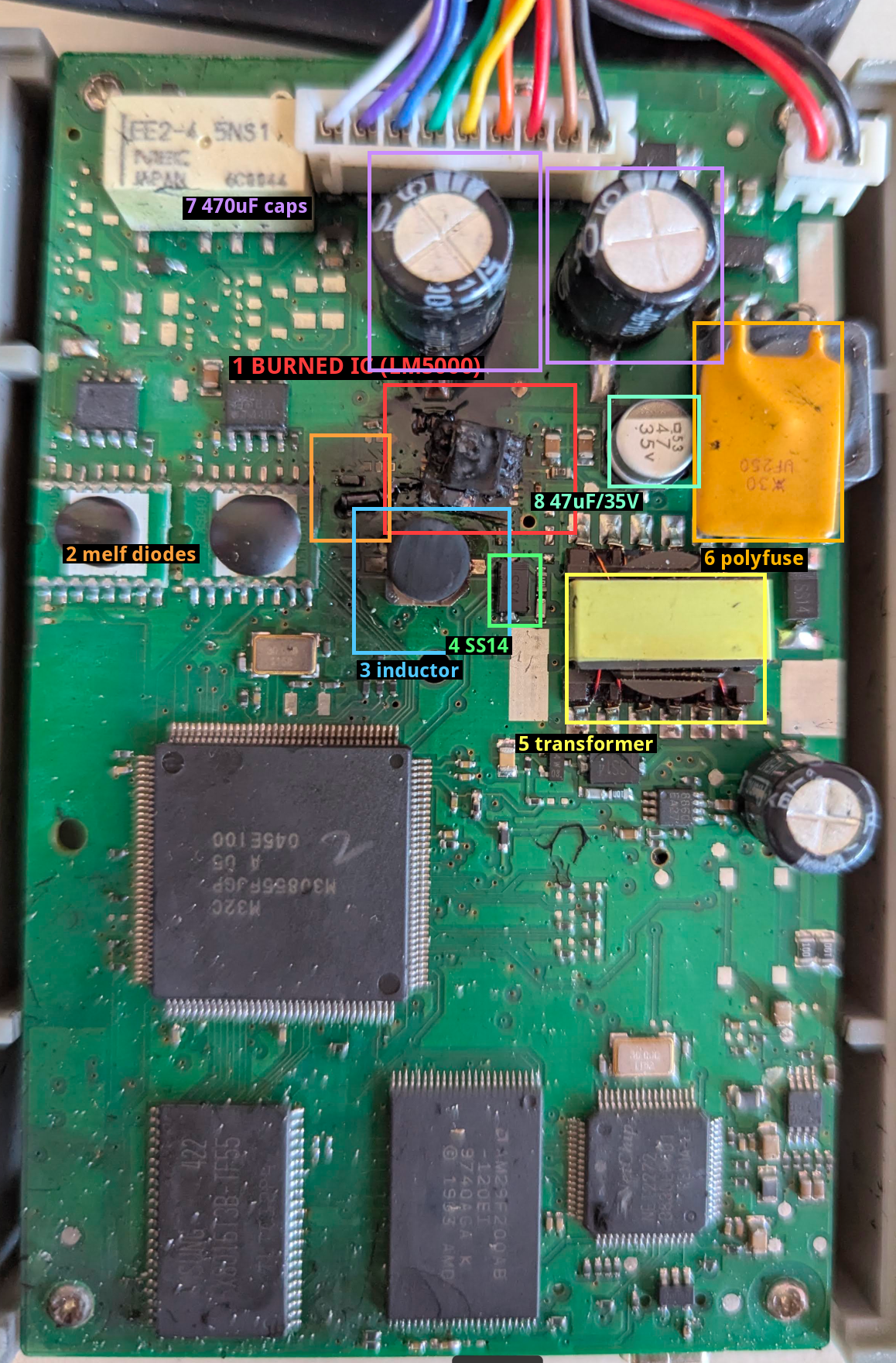
| # | Component | Condition | Action |
|---|---|---|---|
| 1 | LM5000-3MTC flyback regulator | Destroyed (carbonized) | Replace |
| 2 | MELF diodes / passives beside it | Soot-covered, unknown | Test after cleaning; replace if bad |
| 3 | Drum-core inductor (input filter) | Probably OK | Test continuity |
| 4 | SS14 Schottky rectifiers (×3 on board) | Probably OK | Diode-test each |
| 5 | Flyback transformer | Looks intact | Test winding continuity |
| 6 | PolySwitch UF250 resettable fuse | Did its job | Verify < 1 Ω cold |
| 7 | 2 × 470 µF / 35 V input caps | Not bulged | Check for shorts |
| 8 | 47 µF / 35 V cap | In soot zone | Check; replace if damaged |
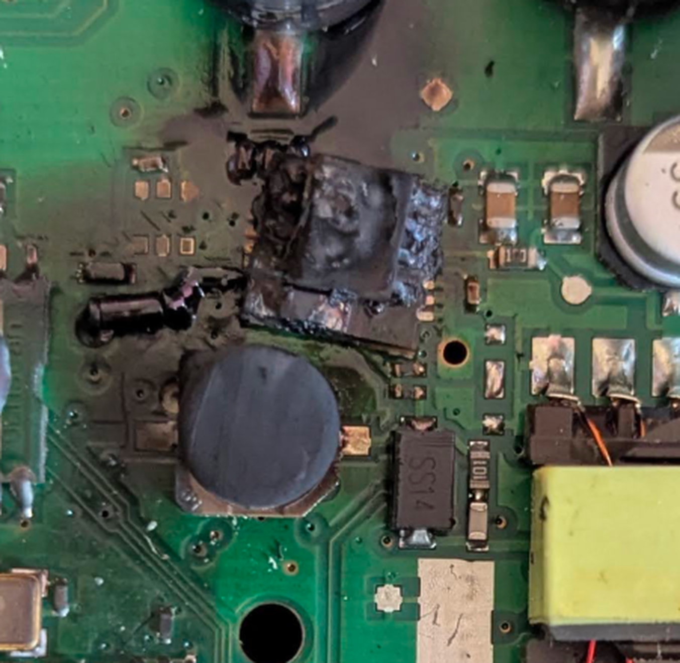
Close-ups of the damage:
| Burned area | Burned IC macro |
|---|---|
 |
 |
Full genuine-board reference photo (useful when rebuilding — your board is identical,
rotated 90°): 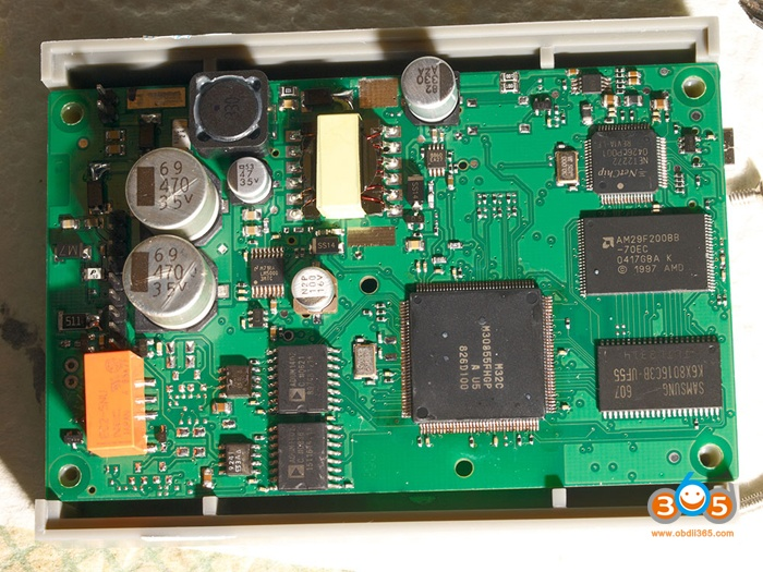
3. Parts & materials shopping list
The IC itself — NOT available in Lithuania, order from a big distributor
Lemona lists only the wrong variant (LM5000SD-6/NOPB, QFN package, minimum order
1000 pcs), so order the correct LM5000-3MTC/NOPB (TSSOP-16, the -3 frequency
variant — this matters, the board's magnetics are designed for it) from one of these.
All ship to Lithuania; buy 2–3 pieces in case the first attempt fails:
| Source | Link | Notes |
|---|---|---|
| Mouser | LM5000-3MTC/NOPB | ≈ €6/pc, ~€20 shipping (free over €50 — top up with consumables) |
| DigiKey | LM5000-3MTC/NOPB | similar terms |
| Farnell LT | LM5000-3MTCX/NOPB | -3MTCX = same chip, tape packaging |
(Avoid AliExpress/eBay for this one — this exact part is a counterfeit magnet.)
Consumables & small parts — Lemona (in stock at time of writing, 2026-07)
| Item | Price | Link |
|---|---|---|
| SS14 Schottky diode, spare (buy 5) | €0.20/pc | lemona.lt |
| Desoldering braid Stannol 1.5 mm | €6.20 | lemona.lt |
| Flux gel, RMA, 14 ml syringe (AG Termopasty) | €18.65 | lemona.lt |
| Solder Sn60/Pb40 0.5 mm 100 g (leaded = much easier for beginners) | €13.90 | lemona.lt |
| Isopropanol PRF IPA 220 ml | €6.70 | lemona.lt |
| 1.5KE33A TVS diode (optional protection upgrade, buy 2) | €0.40/pc | lemona.lt |
| 470 µF / 35 V cap (only if a bulk cap turns out bad) | €0.50 | lemona.lt |
| ESD tweezers (if you don't own any) | €19.90 | lemona.lt |
Lemona has pickup stores in Vilnius, Kaunas, Klaipėda etc. If the 47 µF/35 V SMD cap turns out damaged, add a Panasonic/Nichicon 47 µF ≥ 35 V SMD electrolytic to the Mouser order (Lemona only stocks it in 1200-pc reels).
Tools you need
- Soldering iron with a fine chisel or small bevel tip (2 mm or less), ~320–350 °C
- Multimeter with diode/continuity mode — essential
- Flush cutters or a sharp scalpel/blade
- Magnification: a loupe, or your phone camera in macro mode (works great)
- Old toothbrush (for IPA cleaning), small flat screwdriver (carbon scraping)
- Optional but nice: a 12 V bench supply with current limit for the first power-up
4. Step-by-step repair
Safety: wash hands after handling leaded solder, don't eat at the bench, ventilate the room. Flux smoke shouldn't be inhaled — position your head to the side.
Beginner tip: before touching the DICE, practice for 30 minutes on any scrap PCB (dead router, etc.): remove and re-solder a few small parts. TSSOP soldering is very doable with flux + braid, but not as your first-ever joint.
Step 1 — Document
Take sharp photos of the whole board and the damaged area from several angles before changing anything. You will refer back to them.
Step 2 — Remove the burned chip
The chip is dead, so destructive removal is easiest and safest for the board:
- With flush cutters or a scalpel, cut all pins right at the package body and remove the charred body. Don't pry hard — the pads under it are heat-weakened.
- Remove each leftover pin stub: touch it with the hot iron tip and slide it off the pad with tweezers.
- Clean all pads: apply flux gel, lay desoldering braid over the pads, press with the iron until solder wicks up. Work in short passes; don't scrub or push sideways — lifted pads are the main risk here.
Step 3 — Clean off ALL carbon (critical)
Burned PCB residue is electrically conductive and the repair will not work (or will re-burn) if it remains.
- Scrape the black charred material off with a small flat screwdriver or scalpel until you reach clean laminate / intact green solder mask. Charred solder mask must go too.
- Scrub the whole area with IPA and a toothbrush; wipe with paper towel. Repeat until towels come away clean.
- Verify with the multimeter (ohms, 20 MΩ range): between any two neighbouring bare traces/pads in the cleaned area you should read open / >20 MΩ. Kilo- or megaohm readings = carbon still present, keep scraping.
- Also remove any solder splashes/balls around the area (visible in the macro photo).
Step 4 — Inspect pads and traces
Compare the cleaned footprint with the genuine-board photo (images/05). The TSSOP-16
footprint has 8 pads per side. Check with continuity mode that each surviving pad still
connects where it should (see pinout below). If a pad is missing, scrape solder mask
off its trace nearby and plan to solder a short jumper from the chip pin to the trace —
fiddly but normal repair practice.
LM5000 pinout (from the TI datasheet):
| Pin | Name | Connects to on the board |
|---|---|---|
| 1 | COMP | RC network to ground |
| 2 | FB | feedback resistor divider |
| 3 | SHDN | enable (pulled up / driven) |
| 4 | AGND | ground |
| 5–8 | PGND | ground plane |
| 9–11 | SW | transformer primary |
| 12 | BYP | 100 nF cap to ground |
| 13 | VIN | +12 V rail (470 µF caps / polyfuse side) |
| 14 | SS | soft-start cap |
| 15 | FS | frequency select (grounded = 300 kHz) |
| 16 | TEST | ground |
Orientation check (do this before soldering!): beep out the footprint — the side where four adjacent pads all connect to ground is the pin 1–8 side (pads 5-8). Pin 1 is the pad on that side farthest from the transformer-connected (SW) pads. On the genuine board photo the pin-1 dot faces the small 6-pin chip / away from the transformer — your board must match.
Step 5 — Test the surrounding components
With the multimeter, before installing the new chip:
| Component | Test | Good reading |
|---|---|---|
| SS14 diodes (all 3) | diode mode, both directions | ~0.15–0.35 V forward, OL reverse |
| MELF diodes near burn (item 2) | diode mode | ~0.2–0.7 V fwd, OL reverse. Short/open = replace |
| Drum inductor (item 3) | ohms | ≈ 0–1 Ω |
| Transformer windings | ohms across pin pairs | low ohms (continuity), no winding open |
| PolySwitch fuse (item 6) | ohms | < 1 Ω at room temperature |
| 470 µF caps | ohms across legs | not 0 Ω; reading climbs as cap charges |
| Each supply rail | ohms across each output cap (e.g. the 47 µF, the small electrolytics near transformer) | not near 0 Ω — a hard short here means downstream damage, stop and investigate |
| 12 V input | ohms from OBD pin 16 wire to GND | not a short |
If the sooty MELF diodes measure bad but their markings are unreadable, clean them and photograph — they can usually be identified from the genuine board or by their circuit position (ask for help with the photos before guessing).
Step 6 — Solder the new LM5000
- Apply a thin layer of flux gel to all pads.
- Melt a tiny amount of solder onto one corner pad only.
- Place the chip with tweezers, check orientation (Step 4), align all pins on their pads, then reflow that corner pad while nudging the chip into perfect alignment. Check alignment from both sides with magnification — all 16 pins must sit centered on their pads.
- Tack the diagonally opposite pin. Re-check alignment.
- Solder the rest: more flux, then drag a lightly-loaded iron tip slowly along each row of pins. Solder bridges between pins are normal at this stage.
- Remove bridges: flux on the bridge, clean braid over it, press briefly with the iron.
- Inspect every joint with magnification: each pin wetted to its pad, no bridges. Clean flux off with IPA and inspect again.
Step 7 — Replace collateral parts
Replace anything that failed testing in Step 5 (SS14s are in your Lemona order; MELF diodes identify first — see above). If the 47 µF/35 V cap case is scorched, replace it.
Step 8 — First power-up (bench, not car!)
- Feed 12 V, current-limited to ~300–500 mA into the OBD connector: pin 16 = +12 V, pins 4 & 5 = GND. No bench supply? Use a 12 V DC adapter with a 12 V/5 W automotive bulb in series as a poor man's current limiter, and add a 1 A fuse.
- Nothing should get hot or smoke. Current draw should settle well under the limit.
- Measure voltage across the output caps near the transformer — you should see stable rails (typically 5 V-ish and other low voltages) instead of 0.
- Connect USB to the PC — the device should enumerate.
- Only then test with VIDA on the car.
Step 9 — Optional protection upgrade (recommended)
Solder a 1.5KE33A TVS diode across the 12 V input (cathode/band to +12 V after the polyfuse, anode to GND — it must be reverse-biased in normal operation, verify before powering!). It clamps vehicle voltage spikes above ~33 V that likely killed the LM5000 in the first place. The genuine design tolerates this addition fine.
5. If it doesn't work out — fallbacks
- Pads/traces too destroyed: solder the new LM5000 onto a TSSOP-16 breakout board ("dead-bug" style) and wire its pins to the surviving vias/components with thin wire.
- Beyond rescue: the digital half (MCU/flash/RAM) is fine, so the board is a good parts donor; replacement clone DICE units run ~€60–100.
- Stuck / unsure: clean the board, take sharp macro photos, and ask — the failed small parts can be identified from the genuine-board reference.
6. References
- LM5000 datasheet (TI)
- Genuine vs clone DICE PCB photos (obdii365 blog) — source of the reference images
- MC34063: A tough lesson (mattmillman.com) — the same "regulator fails short and burns until a fuse gives up" failure mode, well explained
- Clone DICE discussion (Matthews Volvo Site)